What is Anderson Bridge?
It is an AC bridge circuit which is used to measure the self inductance of an inductor. With the help of this bridge circuit the inductance of any inductor can be measured accurately. It is a modified form of Maxwell's Inductance CAPACITANCE Bridge, in which capacitors with fixed CAPACITANCE are used instead of variable CAPACITANCE.
How is Anderson Bridge built?
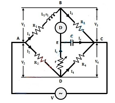
Anderson bridge has four arms as shown in the figure below. An unknown inductor (L1) is connected in series with a resistance (R1) in arm AB of the bridge. The resistance (r1) in this arm is the internal resistance of the inductor. All other known resistance arms are connected to resistance (R2) in AD, resistance (R3) in BC and resistance (R4) in CD.
There is another junction E between the diagonals B and D. A resistance (r) is connected between junctions E and D. A capacitor C of fixed value is connected between E and C. A detector D is connected between E and B which will detect the current flowing between B and E.
Working Principle of Andersen Bridge
Suppose that
Known capacitor = C
Voltage of resistance r = (Vr)
Voltage of capacitor =(Vc)
Known resistance = (R2, R3, R4)
Inductance of unknown inductor =L1
Internal resistance of unknown INDUCTOR = r1
When the bridge is balance, no current will flow through the detector D. Hence Wen Can Write that
Equation (6) and (7) represent Identical current I2 hence
On equating real and Imaganiary part of above equation,We got that
Hence Inductance of inductor in term of CapacitanceAdvantages of Anderson Bridge
- Using a fixed capacitor in an Anderson bridge makes it easy to find the inductance.
- It is easier to balance in Anderson bridge than in Maxwell INDUCTANCE bridge.
- The net value is known as CAPACITANCE as compared to INDUCTANCE.
Disadvantages of Anderson Bridge
- Anderson bridge has more equations to solve than Maxwell bridge.


